Lo Pro Gas Block Pinning

Joined
Jun 20, 2015
Messages
612
Location
Nellis AFB
Ladies & Gents,

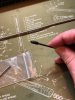
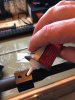
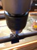
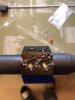
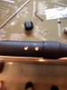
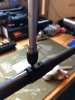
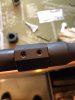
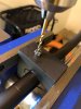
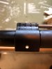
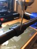
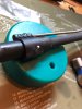
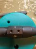
I have always sent my AR barrels and gas blocks to a machinist to get the barrels dimpled for the gas block set screws. I also have them pinned as an extra layer of reliability.

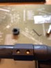
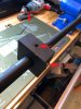
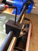
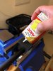
I have been looking at a product for some time and finally decided to pull the trigger and start doing the process my self.

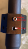
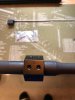
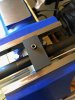
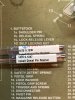
They are pinning jigs for YHM and VLTOR gas blocks and a universal dimppling jig by BRD Engineering.5CD2F2BF-1DBD-482D-AC6E-BA87D6E73857.jpeg


MOD EDIT. This is not an advertisement for sale or service. The intent is meant to be a point of information.
 
Last edited:
So I did the first one last night and broke the drill bit about 3/4 of the way through the pin hole. Came in from the other side and viola!! Going to take it to the range this weekend for a function check and if all goes well, I will post a step by step tutorial.

To be clear, I am no machinist. I am doing all this with the jigs I purchased, a work bench, bench vise and a hand drill.

Just thought some folks might find this helpful with their builds. Sorry for any confusion.
 
Last edited:
Here are the tools needed to sucessfully dimple your barrel for the gas block set screws as well as drilling for the pin.
1. Dowel pin chucking reamer for a 1/8" dowel pin, 0.1247.
2. #31 drill bit.
3. Pinning jig for your model gas block.
4. Blue Loctite.
5. Upper reciver reaction rod. You can use any upper reciever vise block.
6. Bench block.
7. Safety glasses.
8. 11/64" stub legnth drill bit.
9. Dimple jig with correct spacing for your gas block. The one pictured will do .42, .46 and .50 center to center set screw spacing.
10. Cutting oil.
11. 1/8" nail set for driving the dowel pin.
12. Hex (Allen) key set.
Not pictured: an electric hand drill or drill press. I am doing each process with a hand drill.
Tools.jpg
 
Last edited:
Dimpling The Barrel

The first process will be to dimple the barrel for the gas block set screws. This not only ensures perfect gas port alignment but adds a pocket (dimple) for the gas block set screws to sit in to prevent possible rotation.

Remove anything that obstructs access to the gas block. The muzzle device will need to be removed in order to place the jig. The crush washer or peel washer should be replaced when the muzzle device is reinstalled. The gas block will also need to be remover. The gas tube should remain installed on the gas block.

Remove the pointed set screw (Set.jpg) from the dimpling jig and eyeball the gas port on (Block.jpg) the barrel center of the jig's pointed set screw hole. Then snug up the locking set screw on the jig. The pointed set screw is reinserted just enough to make contact with the gas port. Then loosen the locking set screw and wiggle the jig to be sure you are in the hole then tighten the pointed set screw down just enough to remove any wiggle. The pointed set screw will self center in the gas port. Be careful not to over tighten or damage to the gas port may occur. Retighten the locking set screw.

With the jig locked in place the barrel is rotated 180° (Under.jpg) to access the underside. Add a drop of cutting oil (Oil.jpg) to each hole in the jig. The process does not require very much drilling, drill down just to the end of the cutting edge (Drill.jpg) of the 11/64" drill bit. It is easy to see the depth of the dimple (View.jpg) with the jig in place.

Once dimples are complete remove the jig (Dimples.jpg), wipe off excess cutting oil and reinstall the gas block. The barrel will still have the gas port pointed towards the floor. Align the dimples (Align.jpg) with the screw holes in the gas block. The gas block set screws are tapered slightly and will aid in centering the gas port on the barrel with the one in the gas block. Apply a small amount of blue Loctite to the threads of the gas block set screws and snug them up. I used a torque screwdriver set at 20 inch pounds (Final Torque.jpg) but this is not necessary, nice ant tight will do. Done (Done.jpg) son!!

Wipe it all down and you're ready for the pinning process.

Links:
McMaster-Carr
McMaster-Carr
McMaster-Carr
 

Attachments

  • Set.jpg
    Set.jpg
    1.9 MB · Views: 8
  • Block.png
    Block.png
    3.4 MB · Views: 8
  • Under.jpg
    Under.jpg
    887.6 KB · Views: 4
  • Oil.jpg
    Oil.jpg
    1.1 MB · Views: 5
  • Drill.jpg
    Drill.jpg
    1.1 MB · Views: 5
  • View.jpg
    View.jpg
    996.4 KB · Views: 5
  • Dimples.jpg
    Dimples.jpg
    830.5 KB · Views: 5
  • Align.jpg
    Align.jpg
    740 KB · Views: 6
  • Final Torque.jpg
    Final Torque.jpg
    1.1 MB · Views: 6
  • Done.jpg
    Done.jpg
    862.9 KB · Views: 5
Last edited:
Pinning The Gas Block

The process for pinning a low profile gas block involves drilling a hole through the lower portion of the block and a small portion of the barrel. Pinning, in my opinion, is an important aspect of the weapons reliability. That is just my opinion and I know many people that only dimple (often just one dimple under the gas port) and some that feel the set screws are enough. Again, I am not a machinist and consider myself a shade tree armorer at best. This is simply my preference.

Now that the gas block is reinstalled and still upside down, slide the drilling jig over the gas block. Center the gas block in the jig, it should be flush with the front and the back (Flush.jpg) of the gas block. When satisified with jig alignment secure (Secure.jpg) with the set screw that locks against the bottom of the gas block. Remove the upper reciever from the the reaction rod or vise block and place the jig in the vise (Vise.jpg) with the drilling guide up.

Now comes the drilling process with the #31 drill bit. Have a few extra on hand as they will break. Good news is that there is the exit hole on the opposing side with the drill guide so when it does break flip it over and drill the remaining metal out. Put a few drops of cutting oil (Oil.jpg) in the drill guide, insert the drill bit and start to drill. I went slow and after about 20 seconds of drilling (Drill.jpg) I would remove the drill bit from the guide , wipe the shavings off the drill bit and vac out the drill guide to remove metal shavings. Once the drill bit pushes through the other side of the jig you are done drilling. Wipe everything down and remove the gas block from the jig (Hole.jpg).

The hole will need to be reamed in order for the pin to fit as the #31 drill bit is much smaller that the dowel pin. The first two gas blocks I did I used a 0.1247 reamer (1/8" is 0.125) and it ended up being just a little too large as the 1/8" pin pushed through the hole with my finger. I had to order oversized 1/8" dowel pins that were 0.1257 diameter and that fix the issue. On my third block I used a 0.1230 reamer (Reamer.jpg) and the final pin fit was perfect. So, I would recommend having both the 0.1230 & the 01247 reamers. Start with the 0.1230 and if it's too tight use the 0.1247 reamer. Too tight would be hitting the dowel pin like Thor with the hammer and it not going in. Might want to have some of the oversized dowel pins on had as well.

For the reaming process put the upper back on the reaction rod or in a vise block with the pin hole facing up. Put a little cutting fliud on the reamer itself and line it up (Reaming.jpg) with the hole. Going at a moderate speed with steady downward pressue the reamer went right through the hole with ease. I then put the drill in reverse so I did't remove any more metal as I removed the reamer from the hole. Wipe everything down and your ready to install the pin.

Place the barrel and gas block in the groove of the bench block and line up the pin. Check the pin fit by lining up the pin with the hole and give it a few taps with a hammer. If after a few taps it goes in and stands on its own (Start.jpg) you are good to go. Take your 1/8" nail set and drive the pin home (Finished.jpg) centering it in the hole. You now have a gas block the will never move during use.
 

Attachments

  • Flush.jpg
    Flush.jpg
    2.3 MB · Views: 3
  • Secure.jpg
    Secure.jpg
    1 MB · Views: 3
  • Vise.jpg
    Vise.jpg
    1.4 MB · Views: 3
  • Lube.jpg
    Lube.jpg
    1.3 MB · Views: 3
  • Drill.jpg
    Drill.jpg
    1.2 MB · Views: 3
  • Hole.jpg
    Hole.jpg
    860.8 KB · Views: 3
  • Reamers.jpg
    Reamers.jpg
    2.2 MB · Views: 3
  • Reaming.jpg
    Reaming.jpg
    1.2 MB · Views: 4
  • Start.jpg
    Start.jpg
    1.1 MB · Views: 4
  • Finished.jpg
    Finished.jpg
    934.3 KB · Views: 4
Last edited:
Back
Top